This article explains the Blender Procedural Displacement features. We’ll cover how to create and edit a procedural displacement in Blender including using images. Displacement is pretty self explanatory. It is when you change the placement of something. In 3D modeling this usually refers to the change in the location of vertices. You can easily make a displacement yourself by moving a vertex or make a procedural displacement. This means that most of the work surrounding the displacement would be left to the computer. Using this technique you can add a lot of details to your objects without changing all geometry manually. Let’s look how to go about making a procedural displacement yourself.
Creating in Blender Procedural Displacement
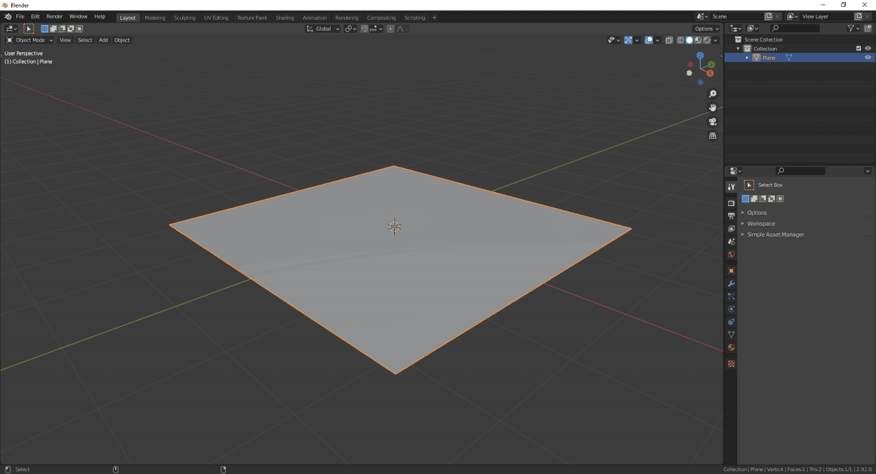
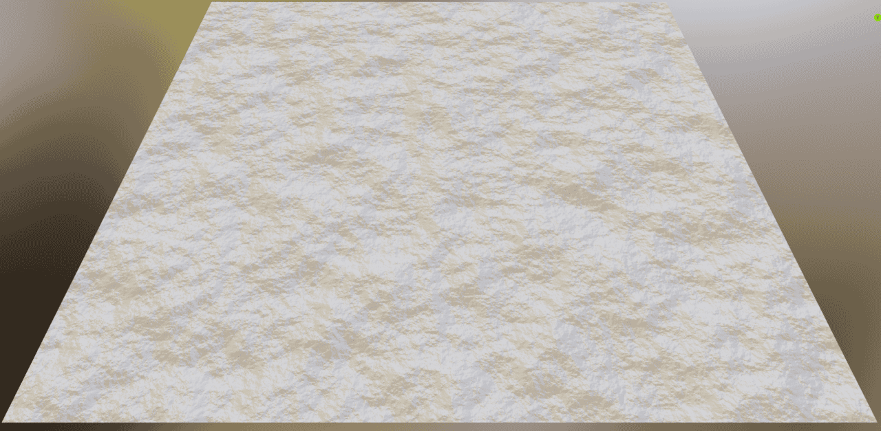
Displacement can be added to basically any object of any shape. But the simplest one to work with and understand is definitely the plane. So the scene is really simple and looks like this:
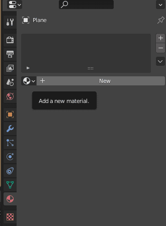
To work with the displacement, we need to have a material. Right now our object does not have one. To add material, you need to open the Material Properties and click on the “+ New” button.
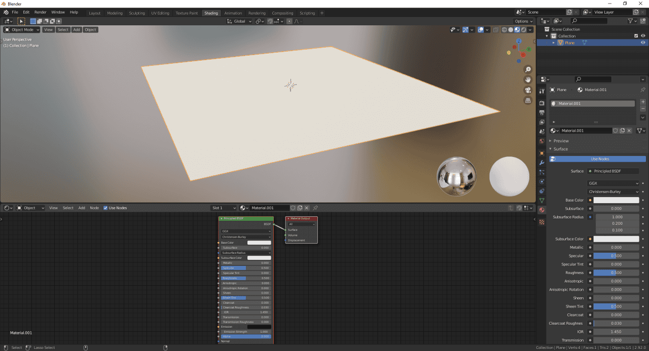
To create a Displacement, we will need to work with the nodes. So either open a Shader Editor yourself, or choose the Shading workspace preset from the top.
Now we will use the Shading Editor and need to create a corresponding Displacement node. Click on the Add > Vector > Displacement.
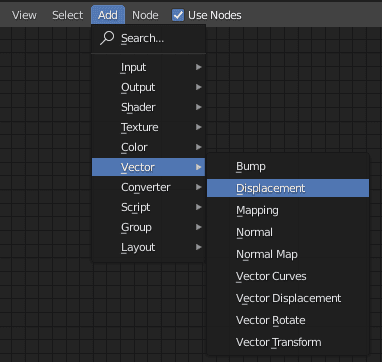
The appeared node has four input options and a single output. We need to have an input, because right now even if we connect this node, it won’t do a thing, as it does not have information about how to displace. This information is stored in the colors, so you can use a texture or an image as input.
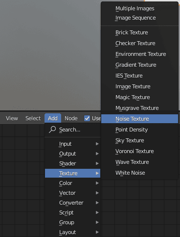
For now let’s stick with the texture. To add a texture node, go to the Add > Texture. Here you can choose basically any that you want, but I would recommend to start with the Noise texture. It is just a random noise consisting of different shapes and colors, exactly what we need.
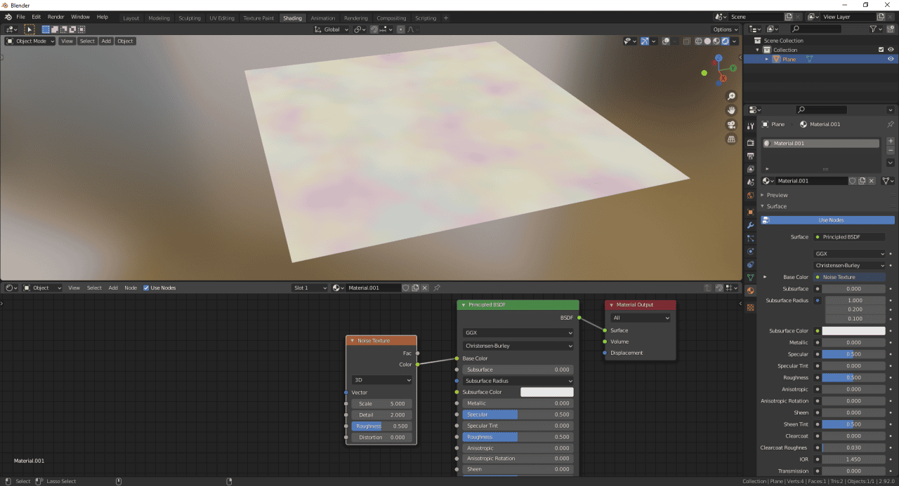
To see what exactly is the noise texture, you can connect its Color output to our material’s color input. After that you will see this texture applied to your object.
Displacement node takes the information of this texture and applies it to an object. Color decides how strong of the displacement we will receive. Black is 0 and is and does not change at all t and white is 1, meaning that it is the maximum displacement. Grey is everything in the middle.
All this means that we don’t need any colors except the black, white and grey. That is why we won’t use the Color output of the Noise Texture, but instead we will use Fac output. It is the black and white version of the same texture.
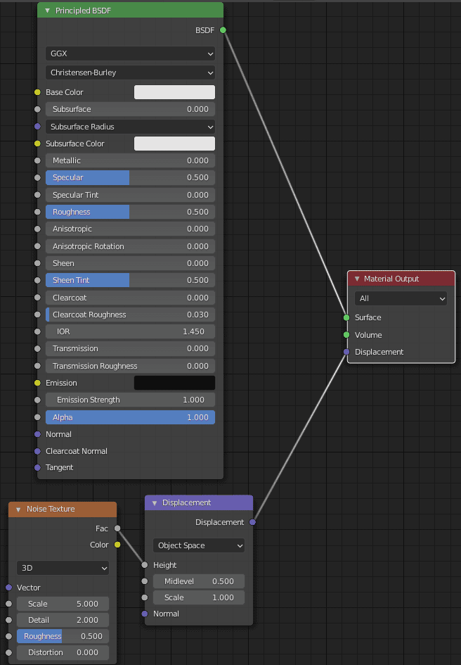
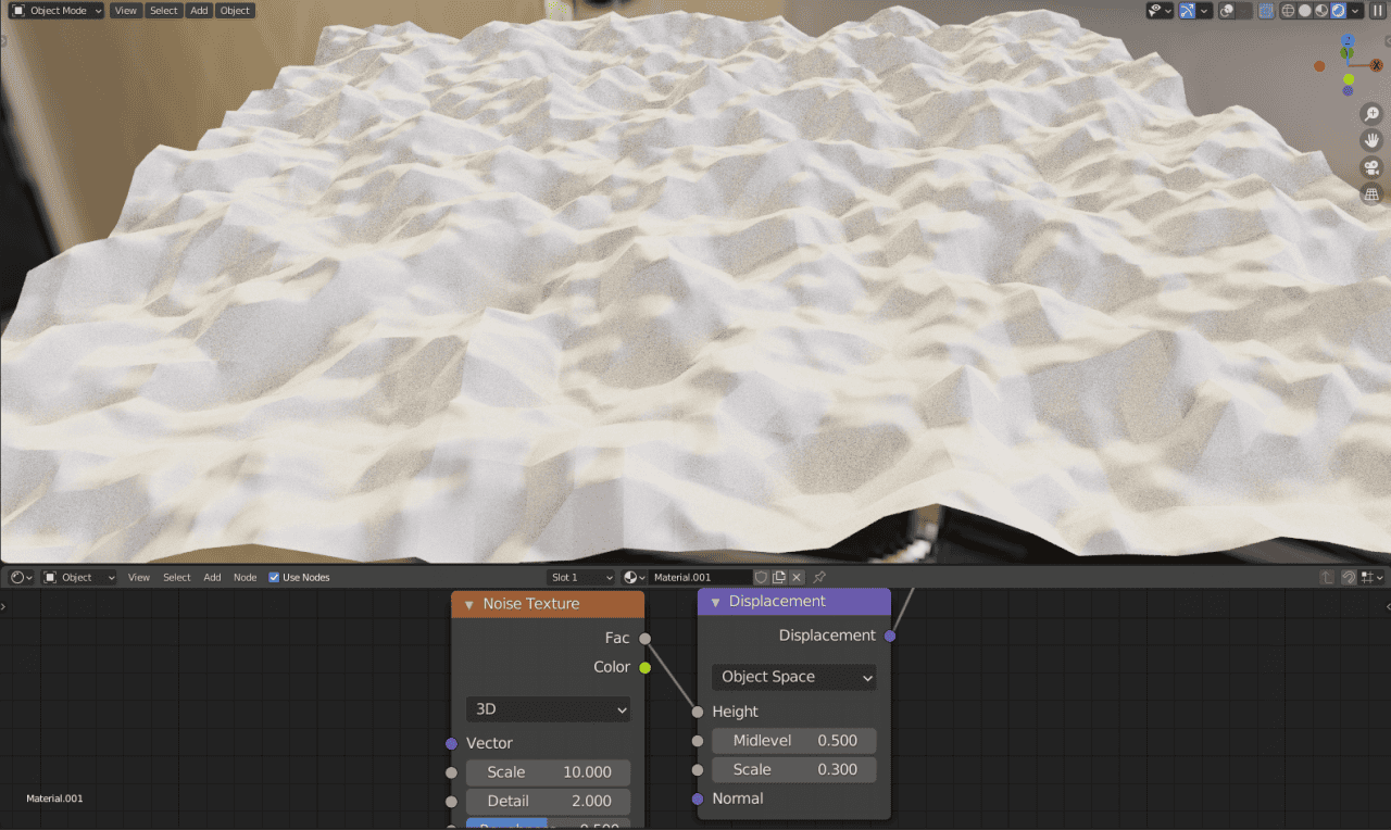
So in the end your Node setup should be like this: Your main shader connected to the Surface input of Material Output, the Fac output of Noise Texture is in the Height input of Displacement node and then it goes to the Displacement input of the Material Output.
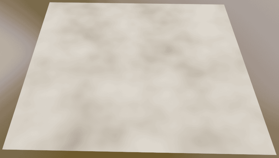
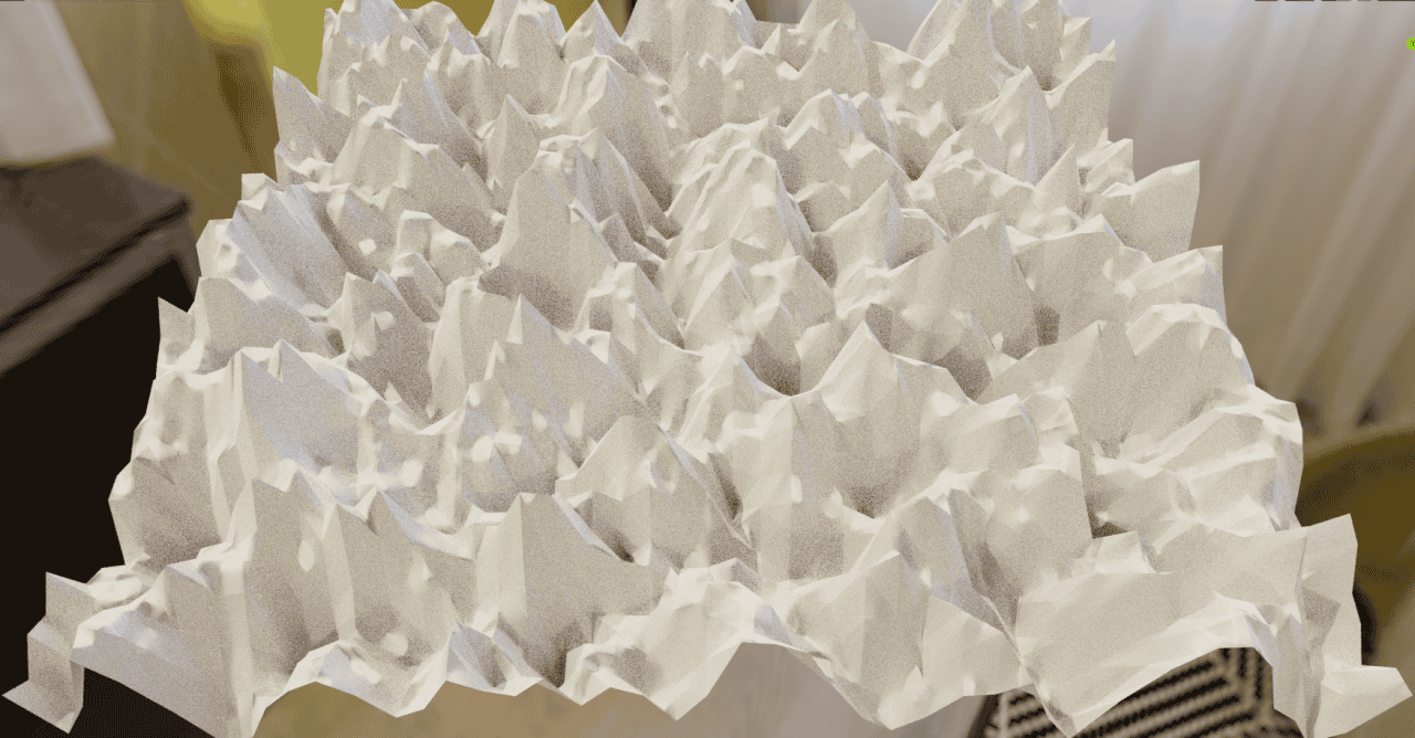
And the object should look something like this:
The displacement is done. Object now looks like it is a bed sheet that was crumpled. But we are not yet finished.
Changing Displacement Settings
You may have noticed that both the Displacement node and Noise Texture have a bunch of settings that you can change. Let’s go through them one by one.
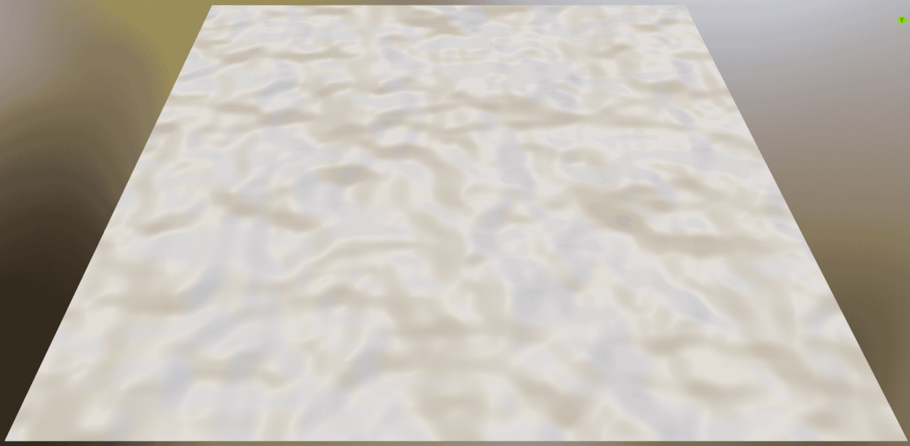
Starting with the Displacement node. The Midlevel option does nothing for now. The Scale option, on other hand, changes the difference between highest and lowest. So if the scale is high – it feels as if the highest and lowest points are really far apart.
The Scale setting on Displacement node
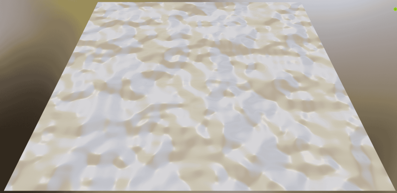
The Scale setting on the Noise Texture node does absolutely different things. It changes the scale of the texture, which influences the displacement. So it makes the displacement either smaller or bigger.
The Scale setting on Texture
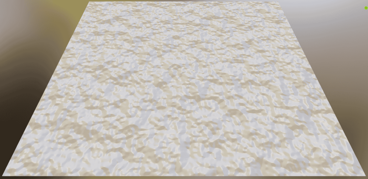
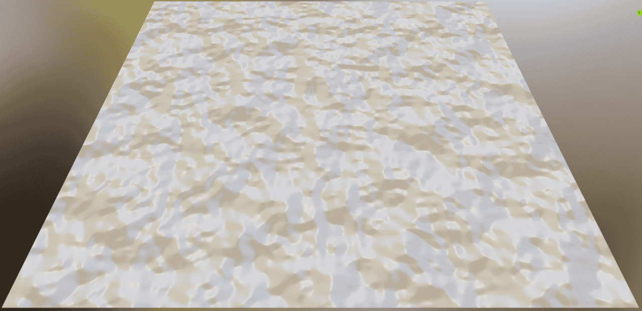
Detail setting changes the level of detail of said textures. High value adds a lot of really small details and bulges.
Detail setting
Roughness works in tandem with Detail setting. So it does either smooth out all the details or makes them more rough.
Roughness setting
The last but not least is Distortion. It is very self explanatory, as it simply adds distortion to the texture. This can lead to some very interesting outcomes.
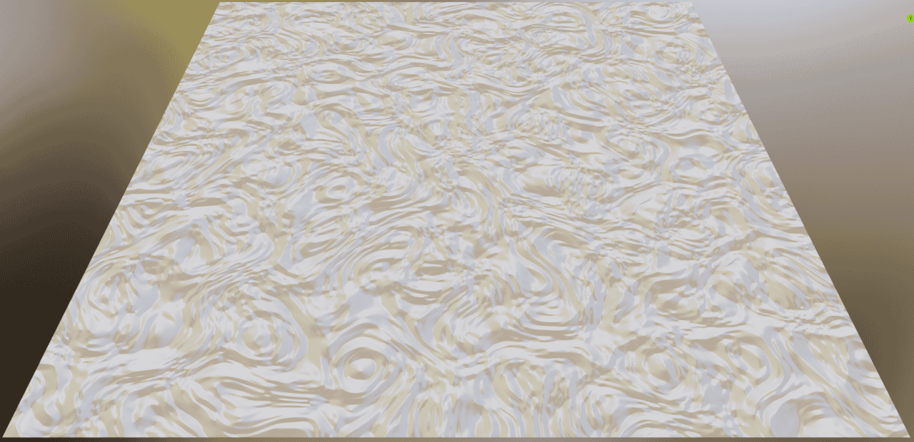
Distortion setting
Adding Volume to a Displacement
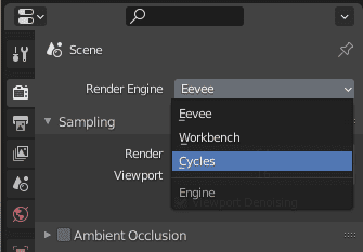
Right now our displacement only looks like it has volume, but actually it does not have any additional geometry at all. To change that and add a real volume – we need to go to the Render Properties and make sure that our Render engine is set to Cycles, as this does not work in Eevee.
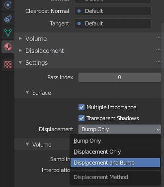
After that go to the Material Properties and near the bottom under the Settings > Surface change Displacement setting from Bump Only to Displacement and Bump.
Right away you should not see any changes. That is because right now we are in the Material Preview shading which uses Eevee to render. And as was mentioned, this change only works in Cycles. So change your shading to the Rendered.
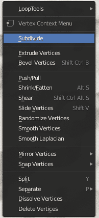
It looks a bit different, but mostly it is the same. This time it is because it is a very simple object. To create real displacements you need to change the location of vertices. Right now our plane consists only of 4 vertices, which is really few. To add more you can either use a Subdivision Surface modifier and apply it or just Subdivide an object a bunch by right clicking on it and choosing the setting.
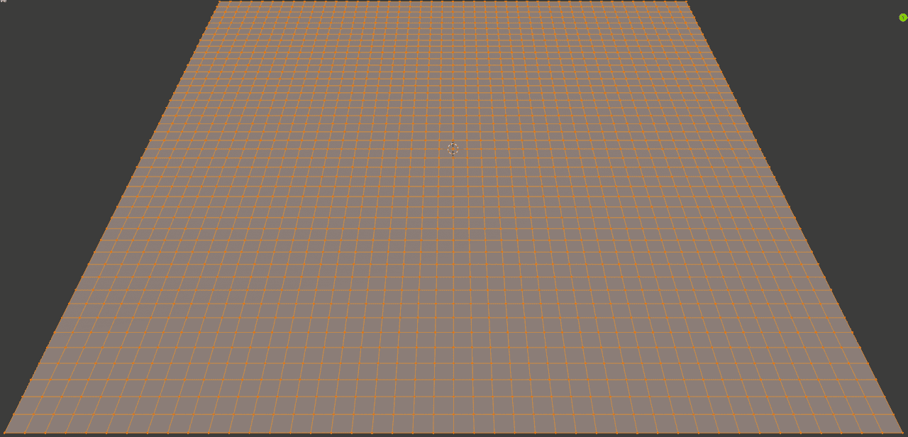
After this your object should have a lot more vertices. The more it has – more detailed the displacement would be, but be careful not to go overboard with this, as it is taxing on the computer. In the end we have something like this or even more:
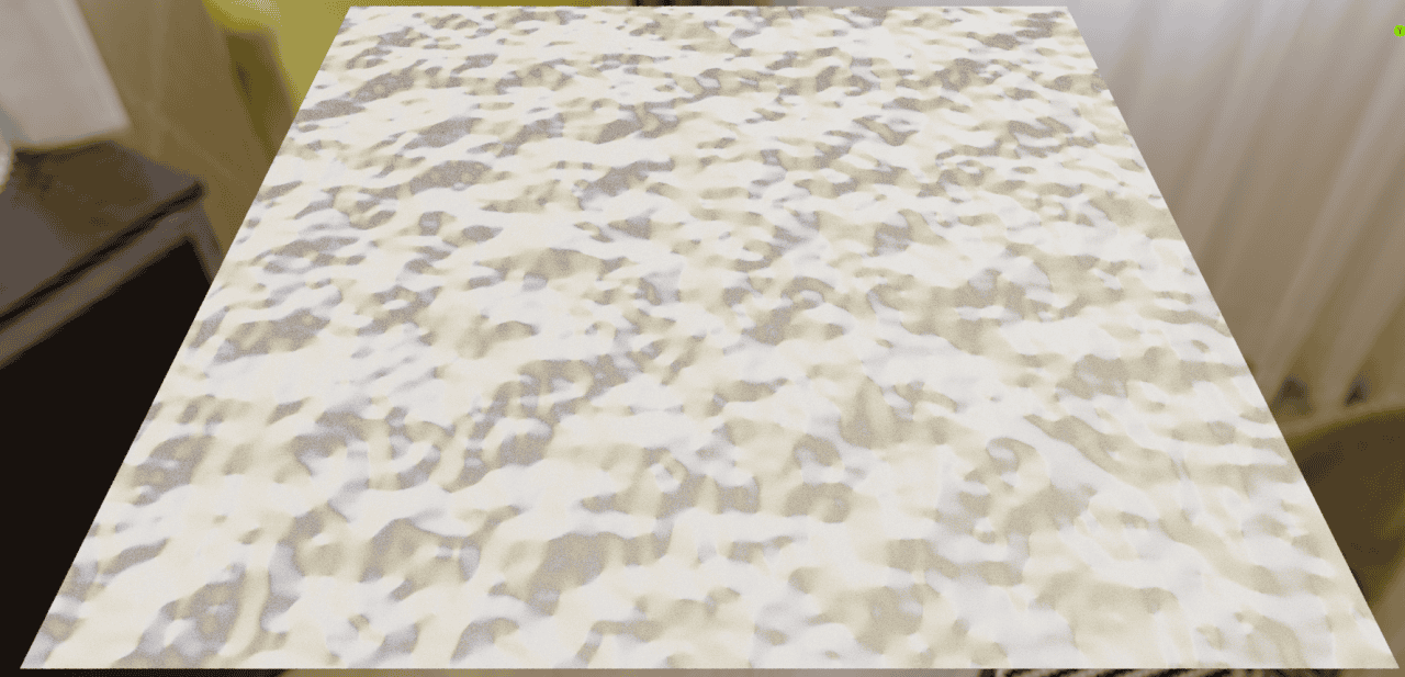
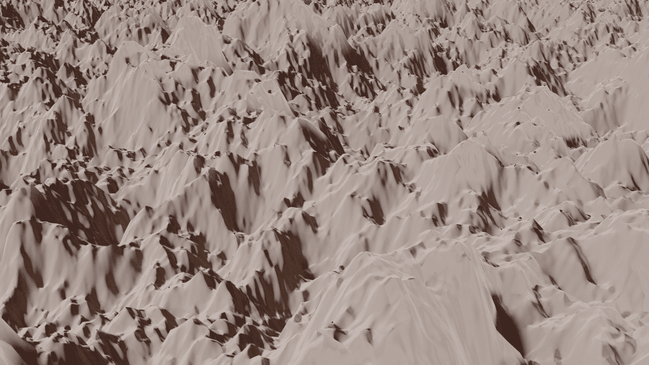
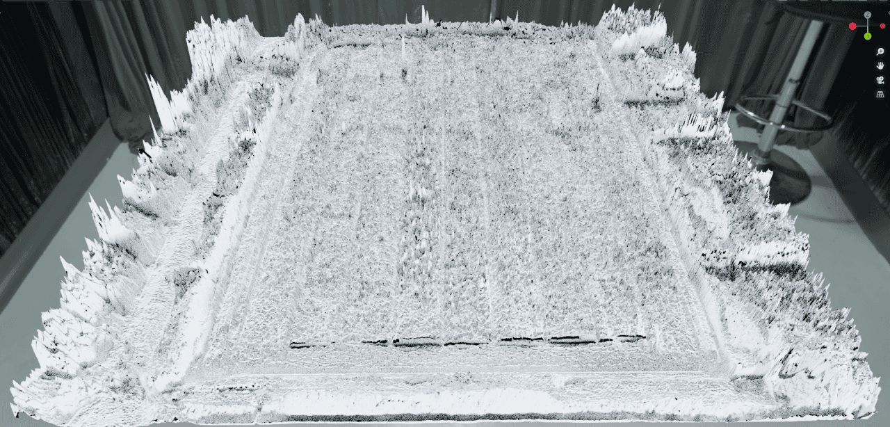
After that when we return to the Rendered shading we will see that the object has changed a lot. It is now very uneven and distorted. Reminds mountains and cliffs.
Most probably this is not what you anticipated. It is far too much of a displacement and looks really distorted. You can control this easily by changing the Scale value of the Displacement node in the Shader Editor. After I lowered the value, it now looks a lot better.
Now finally it looks like a proper displacement. Instead of doing everything manually, we have achieved this result procedurally. And because of this, you can also change the look and feel of current render easily.
All the settings that were mentioned earlier still work and influence this displacement. So you can create something really unique with these techniques. Like some outwardly landscapes.
Making a Displacement out of an Image
Earlier I have mentioned that you also can create a displacement out of an image. This can be any image, but we need to remember and understand that displacement works only on a black and white colors.
So you can’t just feed any image, as for example the random image of a door from Textures.com and expect it to work well.
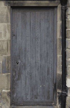
Source Textures.com
Because it will simply not work and the result would be a mess. This image is not appropriate to be used as a displacement map at all.
You can try to fix that by applying some grayscale filter, but it really depends on the image that you are using.
This does not mean that you can’t use images that were not made as displacement maps, because you totally can. It just depends on what you are planning to do with it, what is the desired result. Some images can totally work, as for example this photo of some bricks.
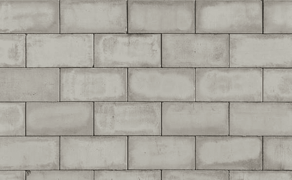
Source Textures.com
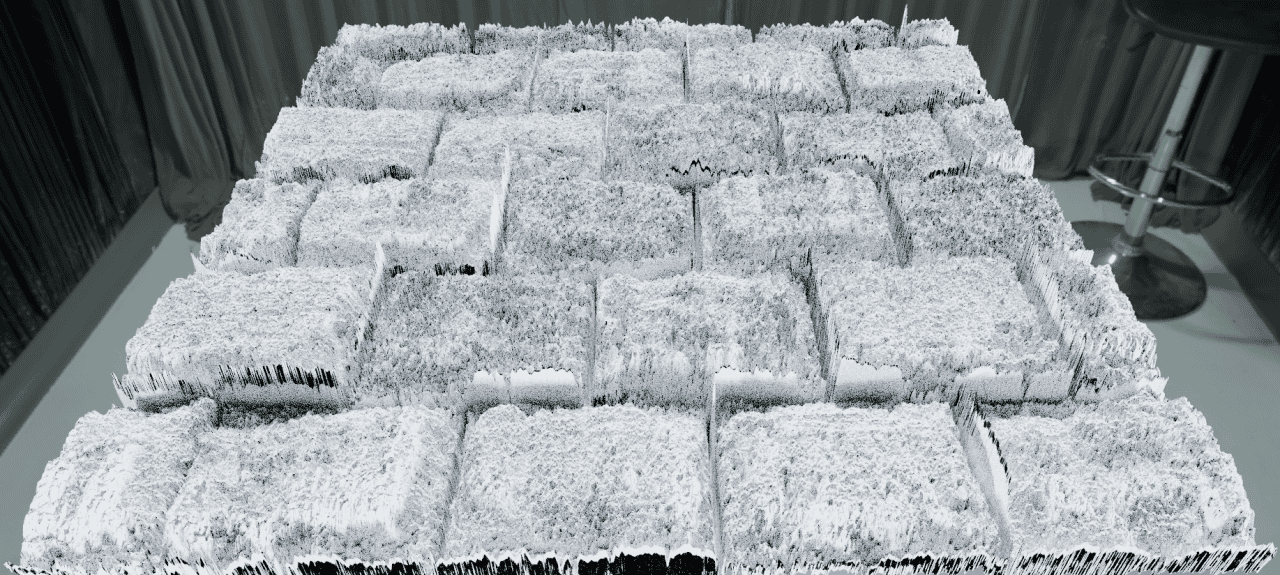
The result of using this image is not ideal, but definitely better than the previous example. You clearly can see that bricks were recreated as displacement.
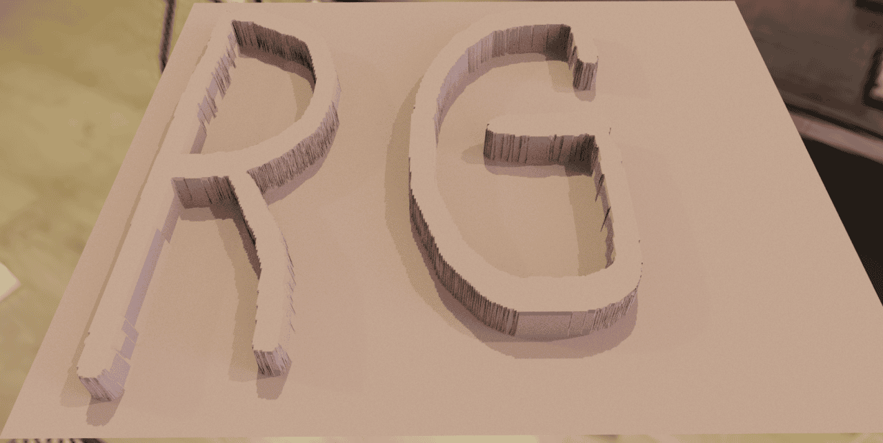
One of the main advantages of this method is that you can just take and create your own images yourself. Just open any image editor software and use black, grey and white colors to draw any shape you want. Then you can apply this as a displacement map to your object.
Conclusion – Blender Procedural Displacement
Displacement is a main action in any kind of 3D modeling. But creating shapes by manually editing vertices each time can be too much. Especially when there are ways to make it a lot faster and easier with the Blender procedural displacement. Hope after this article you understood how to use them and how easy it is to save your time with this. See also our other Blender Tutorials and Top Reviewed 3D Models.